Vibration Course Project
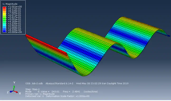 Sixth mode shape of the beam, visualized in ABAQUS
Objective
A cantilever beam must be analyzed to extract natural frequencies of it and determine how it behaves if a mass was added to it. The analyze can be done in 2D and 3D definition of beam model, or with any element type available in ABAQUS suitable for modeling beams.
Problem Definition
There is a cantilever beam with rectangular profile of 3m width, 5cm height and 10m length (a very odd beam indeed!) This beam is made from stainless steel (ST37) with below properties:
- $E = 210 GPa$
- $\nu=0.3$
- $\rho = 7800 \frac{kg}{m^3}$
Since the beam is cantilevered, all degrees of freedoms (DOFs) of one end of this beam must be bounded.
Modeling
In this section a quick review of ABAQUS modeling of the mentioned beam will be presented. Since this report is being written many years later than the actual project, there may be some inaccuracies in it.
The steps to model in ABAQUS are as mentioned below:
- Part (Defining geometry)
- Property (Defining mechanical properties, section and element type)
- Assembly (If there are multiple parts, assembling them together)
- Step (Defining what analysis steps are needed)
- Interaction (Defining interactions between parts)
- Load (Load and boundary condition definition)
- Mesh (Meshing the parts to be analyzed with FEA algorithms)
- job (Defining an analysis job to submit and run)
- Visualization (A separate section for visualizing the results of jobs done on the model)
Part
In this section just a homogenous extruded recangle with respective dimensions as depiced above is made.
Property
In this section, first a material is defined with mechanical and general properties of ST37, containing Young’s module, Possion ratio and density. Then a solid homogenous section is defined to be assigned to the part.
Note: Alternatively we could define the beam as a 2D wire which has a beam profile with rectangular cross section. This definition would be more close to the analytical solutions since there are the same simplification considerations in both methods.
Assembly
Because there is only one part present in this model, the only task to be done in assembling process is to make an instance of the part.
Step
In this section, two steps are defined. One is the frequency step which solves an eigenproblem and extracts natural frequencies of the beam, and the other is the Modal, steady-state dynamics step in which given a force, it calculates the response of the beam in frequency domain and we can extract the FRF plot (Frequency Response Function) of our model from it.
Interaction
Since there is no other parts except the beam, this section is not used in this analysis.
Load
As mentioned previously, there needs to be boundary conditions on one end of the beam, because it is a cantilever beam. It should be noted that in analyzing beams using Euler method, the beam is essentially a plane which is in center of the beam profile, called neutral plane. When applying the boundary conditions it is crucial to assign them to the place where neutral plane lies. Otherwise the result may be different from analytical solutions.
There also needs to be a force which will be activated in “Modal steady-state dynamics” step which in turn gives us the frequency response. It is not important what magnitude this force has, whereas the frequency response will be divided by force magnitude and gives a result independent of force magnitude. This force is prefered to be located at the free end of the beam, on its midplane.
Mesh
Fortunately, because of the simple and straightforward geometry of the beam, there is no need for mesh controls or any kind of tricks, and the built-in meshing system of ABAQUS does the job pretty well and clean. The only note to consider is to verify mesh independency of the results, which will be accomplished by repeating the job with different mesh sizes and comparing the results.
Adding Vibration Absorber
Another task on this project was to add a vibration absorber to the beam and see the difference it makes in both natural frequency shift and frequency response plots. Vibration absorbers are just a mass connected to the system with a spring (or maybe sometimes with damper too) which will absorb the induced vibration on certain frequencies and don’t let the main system vibrates.
)](/project/vibration/vibartion_absorber.gif)
We can add vibration absorber by two methods, one is to add a lump of mass (in form of a box for example, or a sphere) and connect it to the beam. This lump will have both a constant of springness and inertia, so it can be modeled as a vibration absorber. But since this method is too hard and may cause unexpected errors in the result, we can add analytical inertia and spring which will only affect the frequency response and natural frequency shifts without any unexpected effects on our model.
Results
Natural Frequencies
The calculated natural frequencies are showed in the following table:
| Natural Frequencies (Hz) | |
|---|---|
| Mode 1 | 0.043711 |
| Mode 2 | 0.273906 |
| Mode 3 | 0.663628 |
| Mode 4 | 0.766852 |
| Mode 5 | 1.502477 |
FRF Without Vibration Absorber
To prepare FRF plot of the beam 5 nodes on model is chosen, but here to simplify the results, only the node which is from free end of beam is presented:
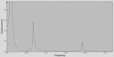
As it is obvious, we can see that in each natural frequency of the beam there is a peak in frequency response of the beam.
FRF With Vibration Absorber
This presented plot is the same as the one from previous section, but with vibration absorber present. As we can seem there is a point in FRF where the vibration magnitude is significantly less than other points. This is because of the vibration absorber effect.
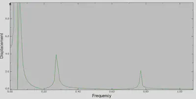
In this project the vibration absorber natural frequency was designed to be the same as the first natural frequency of the beam. This is the reason why in that frequency there is a split in frequency response.
Siavash Emami
Mechanical Engineer
My research interests include mobile robots, SLAM and navigation, path planning and control theory.