Mechatronic Course Project
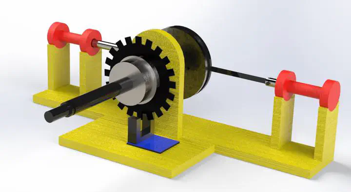 Solidworks model of the solenoid motor
Objective
In this project a solenoid motor must be constructed from scratch and it must be controlled using arduino UNO board and apporpriate sensors. The goal is to optimise the device design and control algorithm to achieve higher rotation speed.
How It Works
Solenoid motors are essentially just a number of solenoids being controlled by either a mechanical or electrical sensor to actuate in an exact moment, pulling inside a rod into themselves and make the torque needed to rotate a flywheel. It is crucial to have a flywheel with sufficient moment of inertia, because otherwise the rotation would be damped real quick before the next actuator (solenoid) gives the next stroke to continue the rotation.
Of course to operate correctly, there needs to be at least a sensor to time the strokes needed for continuing the rotation. If the sensor is mechanical, it can be a camshaft connected to the flywheel, which will make contact with solenoid circuit each time it needs to stroke and makes the electric current flow through it. For each solenoid we need an independent cam on the camshaft.
)](/project/mechatronic/mechanicalsolenoidengine_hu2eb4f0cca87255b16068bd3a5cfe6d3f_77972_11f0024f23aefcfc82d2c38a1aed432c.webp)
Another way to time the strokes is to use a combination of optocounter sensor and transistors. The optocounter will measure the shaft (or flywheel) rotation by counting the amount of interupts caused by a counter disk and whenever the timing is apporpriate, the microcontroller sends a signal to the transistor which acts as a switch, letting the electric current flow through solenoid and make the stroke. This design is relatively less expensive than the mechanical one.
Design
Basics
In this project, it was decided to make the engine two-stroke, and to actuate it with optocounter and transistors. The solenoids were made by winding magnet wires around a hallow 3D printed cylinder and the amount of winding was figured by trial and error (it was the easy way 😄)
The chasis too was 3D printed and the solenoids’ plungers were machined. Since the project was supposed to be low-cost, the shaft, ball-bearing and flywheel were purchased from a store which sells used parts, so they weren’t excatly optimised for this purpose.
Mechanism Design
The whole mechanism is assembled on a 3D printed chasis (as depicted in the cover picture) but the arduino setup is placed outside the assemby and is connected to it by a breadboard.
The chasis should have the place to hold the bearing and have two stands for solenoids. distance between two stands and the hole is of great importance and must have tight tolerance. This is the reason the whole mechanism is modeled in SOLIDWORKS accurately and the parts’ dimensions are extracted from the model.
The hallow cylinders which serve as solenoid shells on the other hand, should have loose tolerances since the solenoid plungers shouldn’t have friction when sliding through them. The length and diameter of shells are also important since the amount of current solenoid draws is directly related to the length of magnet wire used for solenoid. These dimensions are also determined empirically.
Circuit
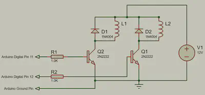
The circuit to control the current is simple and straightforward, but the only point to consider is to make sure there are safety diodes for back-emf caused by solenoids’ activation. These diodes will be placed parallel to the solenoids and in opposite direction of the current flow. When there is a back-emf these diodes will guide the resultant current back into the solenoids to protect the switching transistors. Transistors used in this project were 2N2222 which are high-frequency and suitable for this usage. There is also an approximate schematic of the circuit design provided below:
Challanges
One of the main challanges was the problem with optocounter module which behaved bizarre when sensed intrupt. Arduino would pick up a couple or even three consecutive signals when there was only one interupt. After some searching in internet, found out that there is a noise which arduino interprets as intrupt signal and it should be eliminated from original signal to work correctly. There were two options, one was to use a capacitor as a low-pass filter, the other was a software trick to accept only rising signal intrupt, not the noises. Since we had to do the project with minimum cost, we decided to go with the second option.
Another challange was that the timing needed some tuning. At first, the stroke timing was exactly aligned with the plunger of solenoid being fully out, but apparently if the solenoid activates a little before its plunger reaches the maximum course, the motor will produce more effective torque and drive the shaft faster.
We were notified by one of our classmates that if we used oil to lubricate the plunger rods, they’d have less friction with their shell and motor would work faster.
Result
The motor was constructed and controlled successfully. It reached rotational speed of 660 RPM and our design placed 3rd in the competition between classmates. Of course our design had many flaws, but it was a pleasant experience for everyone.
Siavash Emami
Mechanical Engineer
My research interests include mobile robots, SLAM and navigation, path planning and control theory.