Exercise Box Project
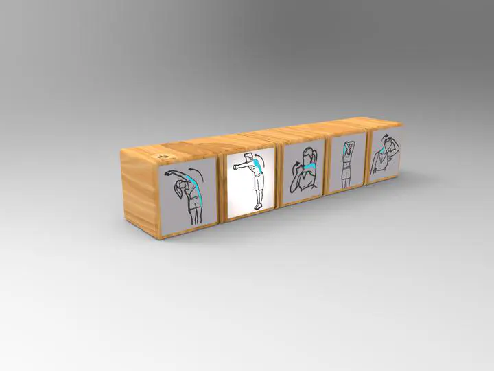 A render image of the exercise box
Objective
This project was assigned by industrial design faculty, and needed an engineer to build the necessary electronic boards for their conceptual design. Their idea was to design a box which user places on their desk and this box will alarm to remind them they have to exercise behind their desks. The box contains four houses, each for a particular type of exercise. behind each housing there is a LED which will be activated on a specified time and a buzzer will alarm for 0.5s to attract the users attention.
Elements
One big challenge in making the board was to find a proper LED which emits enough light to brighten the housing, yet it is also crucial that these LEDs don’t make much heat because the enclosure doesn’t have enough space for air circulation. First, a ribbon of LED was used but it was too hard to solder them and the bunch didn’t have enough stability. So instead, in the second design four COB LEDs were used which made more heat but they were suitable for using in the box.
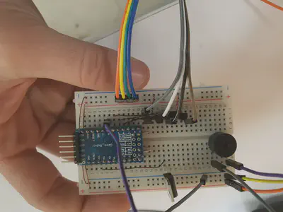
In the initial design it was decided to use a Arduino Mini on a breadboard as the main MCU (MicroController Unit). but because of restrictions breadboard introduce, in the second design a DIP Atmega 328PU was used on a zero PCB. I used Arduino as ISP to program the microcontroller which worked pretty well.
The power supply used is a wall adaptor which outputs 12V DC voltage and maximum 2A current. In order to power the microcontroller there needs to be a regulator which reduces the voltage to nonminal 5V DC. First a linear regulator was used, but I didn’t know how it disipates energy in the form of heat and made the first design smoking 😅 . After re-evaluation it was decided to use Buck regulator which uses PWM signals to reduce voltage and won’t disipate energy. Buck regulators usually make noise in systems but since the circuit doesn’t have any noise-sensetive element, it’s safe to use it.
Four 2N2222 transistors are used to switch current flowing through LEDs. We can’t power the LEDs using microcontroller because they need 12V DC voltage to operate and also they draw huge current and may damage microcontroller.
Other crucial element in this board is the RT (realtime) clock which stores the exact time since they are programmed and can tell the time with good accuracy even if the power supply was disconnected. The clock used is DS1307, but this clock had some issues. This clock uses a lithium ion rechargable battery as power backup, but these batteries are too expensive. Another alternative is to use lithium non-rechargable batteries which are extremely cheaper, but the circuit in clock will force charge it if we use this battery and will damage it, and even can be hazardous since it can catch fire. The solution was to modify clocks circuit and remove some of the pull-up resistors and zener diod in charging circuit and it’s good to go.
Circuit
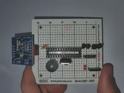
The circuit schematic is pretty straightforward and easy to understand, but to squeeze it into a tiny box it was needed to connect elements in a relatively complex manner. To make it even more compact, I had to use magnet wire as jumpers, because it is very tiny and has good insulation and we can easily pass them on top of each other without making short circuit.
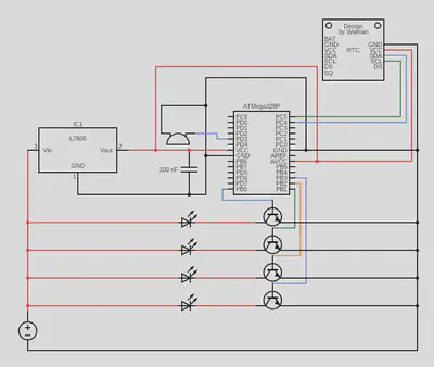
Four digital pins are used to control the transistors and a PWM pin is used for buzzed. The buzzer needs to connect to PWM pin because it produces different sounds with different frequency as input. The RTC needs to connect to analog pins for serial communication (I2C).
Algorithm
The algorithm is easy to impliment too. It is written with arduino IDE and uploaded using arduino as ISP programmer. The MCU is programmed in order to beep once when connected to power (to ensure the program is running correctly) and then it receives current time from RTC, goes through cascaded conditions to determine if it is time to light up the LEDs or not. The conditions will ensure that this device only works saturedays to wednesdays (working days in Iran) and in specified times: 10, 12 and 15.
Siavash Emami
Mechanical Engineer
My research interests include mobile robots, SLAM and navigation, path planning and control theory.